How did you implement UML in your project PART I
What is the sequence of UML diagrams in project?
✍: Guest
First let me say some fact about this question, you can not implement all the nine diagrams
given by UML in one project; you can but can be very rare scenario. The way UML is
implemented in project varies from project to project and company to company.
Second very important point to remember is normally all diagrams are not implemented
in project, but some basic diagrams are important to have in order that project is readable.
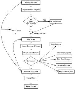
When we talk about projects every project have phases example (Requirements phase,
design phase, coding phase etc ). As every phase of the software cycle proceeds these
diagrams come in picture. Some diagrams span across multiple phases.
Normally following are different basic phases:
Requirement phase (Use Case Diagrams, Activity diagrams)
Requirement phase is the phase where you normally gather requirement and Use Cases
are the best things to make explanation of the system. In requirement phase you can
further make complicated Use Cases more simple and easy to understand by using activity
diagrams, but I do not see it as must in every project. If the Use cases are really complicated
go for a Activity diagram. Example CRUD (creates, read, update and delete) operation
use cases have no significance for making activity diagrams. So in short the outcome
UML documents from requirement phase will be Use Case and Activity diagram documents
(Activity diagram documents will only be there if there are complicated Use Cases to be
simplified).
Not all diagrams are needed in project example: - Activity diagrams will only be needed
when you want some simplified look of a complicated use case.
Design phase (Class diagrams, object diagrams, Component diagrams,
Collaboration diagrams, Deployment diagrams, Sequence diagrams)
Design phase is the phase where you design your technical architecture of your project.
Now again in this you do not use all UML documents of a project.
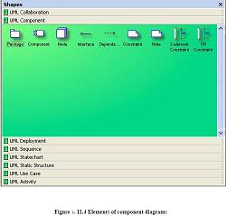
But the next document after the Use Case document will be the Component diagram.
Component diagrams form a high level classification of the system. So after “Use Cases”
just try to come out with a high level classification / grouping of related functionalities.
This should be compulsory diagram as outcome of this document will form
“NAMESPACES” structure of .NET project.
Ok now once your high level grouping is done you can go ahead with class diagrams.
Especially from Use Case you get the “NOUNS” and “VERBS” which can form the class
name and the method name respectively. From my point of view class diagrams should
be compulsory in projects.
Object diagrams are not compulsory it depends on how complicated your project. Object
diagrams shows the relation between instances of class at runtime. In short it captures
the state and relation of classes at any given moment of time. Example you have class
which creates objects of different classes, its like a factory. In class diagram you will only
show that it as a simple class with a method called as “CreateObject”. But in object
diagrams actually you will show the types of instances create from that object.
Collaboration diagrams mainly depict interaction between object to depict some purpose.
I find this diagram to be more useful than Object diagrams as they are addressed for some
purpose example “Login Process” which will use “Login object”, “User Object” etc to
fulfill the login purpose. So if you find the process very complicated go for this diagram.
I see as a thumb rule if there is an activity diagram which show some serious complicated
scenarios. I will like to go for this diagram in order to simplify the explanation.
State chart diagram is again created if your project requires it. If your project has some
complicated start and end states to show then this diagram is most useful. Recently I was
making a call center project where the agent phone pickup and hang state has to be
depicted. So my first state was when agent picks up the p
2007-10-26, 7724👍, 0💬
Related Topics: